
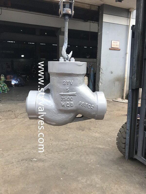
Lift Check Valve 2500LB WCB Body DN125 Weld End: Technical Specifications & Applications

High-pressure lift check valve with 2500LB WCB body and weld end connections
Understanding Lift Check Valve Technology and Applications
Lift check valves operate on a simple yet effective principle: they allow media to flow in one direction while preventing reverse flow through vertical disc movement. Unlike swing check valves that use a hinged disc, lift check valves employ a disc that moves parallel to the flow, providing more reliable sealing in high-pressure applications.

Cutaway view showing the internal mechanism of a lift check valve
The 2500LB pressure class designation indicates these valves are designed for extreme pressure conditions up to 6170 PSI (425 bar) at ambient temperatures, with appropriate derating at elevated temperatures. This makes them suitable for critical applications where system integrity must be maintained under severe operating conditions.
Key Applications for 2500LB Lift Check Valves
- High-pressure boiler feedwater systems
- Refinery process lines with extreme pressure requirements
- Chemical processing with corrosive media
- Offshore oil and gas production platforms
- Power generation steam systems
- Natural gas compression stations
- High-pressure water injection systems
- Petrochemical process lines
- Pressure seal bonnet applications
- Critical service where leakage prevention is essential
Need a Lift Check Valve for Your High-Pressure Application?
Our engineering team can help you select the right valve specifications for your system requirements.
2500LB Pressure Rating: Performance Under Extreme Conditions
The 2500LB pressure class represents one of the highest standard pressure ratings available for industrial valves. This classification follows the ASME B16.34 standard, which defines pressure-temperature ratings for flanged and butt-welding end valves.

Pressure testing of a 2500LB lift check valve to verify performance specifications
At room temperature (38°C/100°F), a 2500LB class valve can withstand pressures up to 6170 PSI (425 bar). However, as operating temperatures increase, the maximum allowable working pressure decreases according to the material’s temperature-pressure curve.
| Temperature | Maximum Allowable Pressure (WCB Material) | Safety Factor |
| -29°C to 38°C (-20°F to 100°F) | 6170 PSI (425 bar) | 1.5 |
| 100°C (212°F) | 5660 PSI (390 bar) | 1.5 |
| 200°C (392°F) | 5160 PSI (356 bar) | 1.5 |
| 300°C (572°F) | 4600 PSI (317 bar) | 1.5 |
| 400°C (752°F) | 3600 PSI (248 bar) | 1.5 |
Pressure Testing and Certification
Each 2500LB lift check valve undergoes rigorous testing according to API 598 and API 6D standards. This includes hydrostatic shell testing at 1.5 times the rated pressure and seat testing at 1.1 times the rated pressure. Additional testing may include:
- Low-pressure air seat testing to verify zero leakage
- High-temperature testing for thermal cycling performance
- Extended cycle testing to verify long-term reliability
- Material certification and traceability documentation

Pressure-temperature rating curve for 2500LB WCB material according to ASME B16.34
WCB Body Material: Durability in Demanding Environments
WCB (ASTM A216 Grade WCB) is a cast carbon steel material widely used in high-pressure valve applications due to its excellent combination of strength, weldability, and cost-effectiveness. For 2500LB lift check valves, WCB provides the necessary mechanical properties to withstand extreme pressures while maintaining structural integrity.

WCB cast carbon steel material used in high-pressure valve bodies
Key Properties of WCB Material for Valve Applications
| Property | Value | Significance in Valve Applications |
| Tensile Strength | 70,000 PSI (483 MPa) minimum | Ensures structural integrity under high pressure |
| Yield Strength | 36,000 PSI (248 MPa) minimum | Prevents permanent deformation during pressure cycles |
| Verlängerung | 22% minimum | Provides ductility to resist brittle failure |
| Carbon Content | 0.30% maximum | Ensures good weldability for weld-end connections |
| Temperature Range | -29°C to 427°C (-20°F to 800°F) | Wide operating temperature range for various applications |
For applications requiring enhanced corrosion resistance or higher temperature capabilities, alternative materials such as CF8M (316 stainless steel), CF8 (304 stainless steel), or special alloys may be substituted. However, WCB remains the standard material for most high-pressure applications due to its excellent cost-to-performance ratio.
Advantages of WCB Material
- Excellent strength-to-weight ratio
- Good weldability for weld-end connections
- Cost-effective compared to alloy alternatives
- Readily available with short lead times
- Proven track record in high-pressure applications
Limitations of WCB Material
- Limited corrosion resistance in aggressive media
- Not suitable for cryogenic applications
- May require special coatings for certain environments
- Lower temperature rating than some alloy alternatives
- Not recommended for highly oxidizing services
Need Expert Material Selection Assistance?
Our metallurgists can help determine if WCB is suitable for your specific application or recommend alternative materials.
DN125 Size Specifications and Flow Characteristics
DN125 corresponds to a nominal pipe size of 5 inches (127mm) in the international pipe sizing system. For lift check valves in this size range, several key dimensional and flow parameters must be considered to ensure proper system integration and performance.

Dimensional drawing of DN125 (5-inch) lift check valve with key measurements
Key Dimensional Specifications for DN125 (5-inch) Lift Check Valves
| Dimension | Measurement | Standard Reference |
| Face-to-Face Length (Butt Weld) | 400mm (15.75 inches) | ASME B16.10 |
| Body Outside Diameter | 245mm (9.65 inches) | Manufacturer Standard |
| Bore Diameter | 125mm (4.92 inches) | ASME B16.34 |
| Wall Thickness (Min) | 22mm (0.87 inches) | ASME B16.34 |
| End Preparation | Per Schedule 160 pipe | ASME B16.25 |
Flow Characteristics and Capacity
The flow capacity of a DN125 lift check valve is determined by its flow coefficient (Cv), which represents the flow rate of water in US gallons per minute that will cause a pressure drop of 1 PSI across the valve. For a typical DN125 (5-inch) lift check valve with full port design:

Flow coefficient (Cv) curve for DN125 lift check valve
- Typical Cv value: 520-580 (depending on internal design)
- Maximum flow rate: Up to 2,900 GPM (660 m³/h) at 10 ft/s velocity
- Minimum flow for stable operation: 290 GPM (66 m³/h)
- Cracking pressure: 0.5-2 PSI (adjustable with spring selection)
- Full opening pressure: 5-10 PSI above cracking pressure
When selecting a DN125 lift check valve, it’s essential to consider the system’s maximum and minimum flow rates to ensure stable operation and prevent issues like valve flutter or water hammer that can occur when the valve operates near its cracking pressure.
Weld End Connections: Installation and Integrity Considerations
Weld end connections are preferred for high-pressure applications like 2500LB class valves because they eliminate potential leak paths associated with flanged connections. For DN125 lift check valves, the weld end preparation follows ASME B16.25 standards, which specify the dimensions and geometry of the weld preparation.

Weld end preparation detail showing bevel angle and dimensions
Weld End Preparation Specifications
| Parameter | Spezifikation | Standard |
| Bevel Angle | 30° ± 2.5° | ASME B16.25 |
| Root Face | 1.6mm ± 0.8mm (1/16″ ± 1/32″) | ASME B16.25 |
| End Thickness | Matches Schedule 160 pipe | ASME B36.10M |
| Surface Finish | 125-250 RMS | ASME B46.1 |
| Material Compatibility | P-Number 1 (WCB) | ASME BPVC Section IX |
Welding Procedures and Considerations
When installing a DN125 lift check valve with weld ends, proper welding procedures are critical to ensure joint integrity and valve performance. Key considerations include:
Pre-Welding Requirements
- Verify valve orientation before welding
- Ensure valve is in fully open position
- Protect valve internals from weld spatter
- Maintain proper alignment with piping
- Verify material compatibility with piping
Welding Process Recommendations
- Use GTAW (TIG) for root pass
- SMAW or FCAW for fill and cap passes
- Control interpass temperature (250°C max)
- Implement proper heat treatment if required
- Perform 100% radiographic testing of welds

Professional welding of a DN125 lift check valve into a high-pressure pipeline
Important Safety Note: All welding procedures for 2500LB class valves must be performed by certified welders following qualified welding procedure specifications (WPS) in accordance with ASME BPVC Section IX. Post-weld heat treatment may be required depending on wall thickness and material specifications.
Need Installation Support for Your High-Pressure Valve?
Our field service engineers can provide on-site supervision and technical support for critical valve installations.
Technical Comparison: Lift Check Valve vs. Alternative Designs
When selecting a check valve for high-pressure applications, several design options are available. Understanding the comparative advantages of lift check valves versus swing, piston, and dual plate designs is essential for making the optimal selection for your specific requirements.

Comparison of four common check valve designs showing internal mechanisms
| Feature | Lift Check Valve | Rückschlagventil | Kolbenrückschlagventil | Doppelplatten-Rückschlagventil |
| Druckrate | Excellent (Up to Class 2500) | Good (Up to Class 2500) | Excellent (Up to Class 2500) | Moderate (Up to Class 900) |
| Flow Resistance | Moderate | Low | High | Low |
| Closure Speed | Fast | Slow | Very Fast | Fast |
| Installation Orientation | Horizontal or Vertical (flow up) | Horizontal only | Any orientation | Horizontal or Vertical |
| Space Requirements | Compact | Large | Very Compact | Very Compact |
| Suitable for Pulsating Flow | Good | Poor | Excellent | Fair |
| Maintenance Requirements | Moderate | Low | High | Low |
When to Select a Lift Check Valve for 2500LB Applications
Lift check valves are particularly well-suited for high-pressure applications with the following characteristics:
- Systems with frequent pressure reversals requiring fast closure
- Applications where space constraints make swing check valves impractical
- Vertical flow-up installations where swing check valves cannot be used
- Services with clean media (minimal solids or particulates)
- Applications requiring positive shutoff with zero leakage

Decision flowchart for selecting the optimal check valve design based on application requirements
Industry Standards and Compliance Requirements
Lift check valves with 2500LB pressure class ratings must comply with numerous industry standards to ensure safety, reliability, and interchangeability. These standards govern design, materials, testing, and quality assurance requirements.
Key Standards for 2500LB Lift Check Valves
| Standard | Title | Scope |
| ASME B16.34 | Valves – Flanged, Threaded, and Welding End | Design, dimensions, tolerances, materials, and pressure-temperature ratings |
| API 6D | Pipeline and Piping Valves | Design, manufacturing, assembly, testing, and documentation requirements |
| API 598 | Valve Inspection and Testing | Inspection, examination, supplementary examinations, and pressure test requirements |
| ASME B16.10 | Face-to-Face and End-to-End Dimensions of Valves | Standardized dimensions for valve interchangeability |
| ASME B16.25 | Buttwelding Ends | Preparation dimensions for welding end valves |
| MSS SP-61 | Pressure Testing of Valves | Hydrostatic testing procedures and acceptance criteria |

Quality control inspection of a 2500LB lift check valve during manufacturing
Required Documentation and Certification
For critical high-pressure applications, comprehensive documentation is essential to verify compliance with applicable standards. Standard documentation packages for 2500LB lift check valves typically include:
- Material Test Reports (MTR) for pressure-containing components
- Hydrostatic and seat test certificates per API 598
- Positive Material Identification (PMI) reports
- Nondestructive Examination (NDE) reports for critical welds
- Dimension inspection reports
- Declaration of Conformity to applicable standards
- ASME B16.34 compliance certification
Regulatory Compliance Note: In addition to industry standards, high-pressure valves may need to comply with regional regulations such as the Pressure Equipment Directive (PED) in Europe, ASME Boiler and Pressure Vessel Code in North America, or other local requirements. Always verify regulatory compliance requirements for your specific application and location.
Maintenance Requirements and Service Life Considerations
Proper maintenance is essential to ensure the reliable operation and extended service life of 2500LB lift check valves. With appropriate care and periodic inspection, these valves can provide 15-20 years of service in most applications.

Maintenance technician performing inspection and service on a 2500LB lift check valve
Recommended Maintenance Schedule
| Maintenance Activity | Frequency | Procedure |
| Visual External Inspection | Every 6 months | Check for external leakage, corrosion, or damage to body and connections |
| Operational Verification | Annually | Verify proper opening and closing during normal system operation |
| Internal Inspection | Every 3-5 years | Disassemble valve to inspect disc, seat, and internal components for wear or damage |
| Seat Lapping/Reconditioning | As needed based on inspection | Recondition seating surfaces to restore proper sealing |
| Spring Replacement | Every 8-10 years | Replace spring to maintain proper cracking pressure and response |
Common Issues and Troubleshooting
Potential Problems
- Leakage through seat
- Valve chatter or instability
- Slow closure response
- Excessive pressure drop
- Sticking or binding of disc
Diagnostic Approaches
- Acoustic monitoring for internal leakage
- Flow analysis for pressure drop issues
- Visual inspection for wear patterns
- Spring force measurement
- Seat and disc surface inspection
With proper maintenance and periodic inspection, 2500LB lift check valves can provide reliable service in demanding applications for 15-20 years. However, service life can be significantly affected by factors such as media corrosiveness, cycling frequency, temperature fluctuations, and proper installation.
Selection Guide and Installation Best Practices
Selecting the right lift check valve for your high-pressure application requires careful consideration of multiple factors. This selection guide provides a systematic approach to ensure the valve meets all technical and operational requirements.

Properly installed DN125 lift check valve showing correct orientation and support
Key Selection Parameters
- System Design Pressure and Temperature: Verify that the 2500LB pressure class is appropriate for your maximum system pressure and temperature combination.
- Flow Characteristics: Calculate minimum and maximum flow rates to ensure they fall within the valve’s operating range.
- Media Compatibility: Confirm that WCB material is suitable for the process media or consider alternative materials if needed.
- Installation Orientation: Determine if the valve will be installed horizontally or vertically (flow up) and select appropriate internal configuration.
- Cracking Pressure Requirements: Specify the required cracking pressure based on system characteristics.
- Space Constraints: Verify that sufficient space is available for installation and future maintenance.
- Special Requirements: Identify any special requirements such as fire-safe design, extended bonnet, or special testing.
Installation Best Practices
Do’s
- Install with flow arrow in correct direction
- Provide adequate support to prevent pipeline stress
- Allow sufficient clearance for maintenance
- Clean piping system before installation
- Use proper welding procedures
Don’ts
- Don’t install near elbows or flow disturbances
- Don’t use valve as pipe support
- Don’t force alignment during installation
- Don’t exceed temperature limits during welding
- Don’t install without verifying flow direction

Installation diagram showing proper orientation and clearance requirements
Installation Tip: For 2500LB class lift check valves, it’s recommended to install a strainer upstream to protect the valve from debris that could damage the seating surfaces or impede proper operation. Additionally, consider installing isolation valves on both sides to facilitate future maintenance without complete system shutdown.
Conclusion: Ensuring Reliable Performance in High-Pressure Applications
Lift check valves with 2500LB pressure class, WCB body material, DN125 size, and weld end connections represent a specialized solution for demanding industrial applications where reliable backflow prevention is critical. By understanding the technical specifications, installation requirements, and maintenance considerations outlined in this guide, engineers and procurement specialists can make informed decisions to ensure optimal system performance and longevity.
When properly specified, installed, and maintained, these high-performance valves provide exceptional reliability in extreme pressure environments, protecting critical equipment and ensuring process integrity. For specific application assistance or technical support, our engineering team is available to provide expert guidance tailored to your unique requirements.
Ready to Specify Your High-Pressure Valve Solution?
Contact our technical specialists today for expert assistance with your valve selection, installation, or maintenance requirements.

")